|
|
|
Usuarios conectados
Actualmente hay 5880 visitantes online. |
|
Productos
|
|
Información
|
|
Destacado
|
|
|
 |
|
|
No hay comentarios de productos.
BUSH 7310/A
Matrix
Item See Model Book
6 6 6 Disassembly Instructions .................................................................. Bush 7310 Mechanical Adjustments ................................................................... Bush 7310 Deck Exploded View .......................................................................... Bush 7310 4. Remove the Locker Spring. 5. Unlock support (2). 6. Remove the Locker R.
1
NOTES 1. Installation of Reel Disk after performing step 1, 2 and 3 in section 2-7 of DISASSEMBLY INSTRUCTIONS. 2.The Height Adjustment washers are sometimes attached to the back of the Reel Disk. 3.Clean the Reel Disk Shaft and put in height adjusting washers. 4. Be careful not to damage the Tension Band Assy at the time of removal and installation. 5. Be careful not to scratch the Reel Disk Shaft with the polyslider washer or the tool at the time of removal and installation. 6. After oiling (Kyoudo oil slaidasu #150) the Reel Disk Shaft, install the new Reel Disk S and Reel Disk T again. 7. After installation, adjust the height of the Reel Disk. (Refer to item 1-1 of MECHANICAL ADJUSTMENTS) 8. After installation, adjust and confirm the tension post position. (Refer to item 1-2 of MECHANICAL ADJUSTMENTS)
U-View Limited
Customer remote control and the PLAY button on the set simultaneously until the indicator ATR disappears. If the indicator ATR disappears, the adjustment is finished. (If the ATR indicator is still illuminated) 1. Connect CH-1 on the oscilloscope to TP4001 and CH-2 to Pin 19 of J4501. 2. Press the PG AUTO key. (JG155) 3. While the ATR indicator is flashing, press the PG MANUAL key. (JG155) 4. Adjust the Tracking +/- key until waveform of the oscilloscope measures 6.5 ± 0.5(H) at both leading and trailing edges. (Refer to Fig. 3-1-A, B) 5. Press the Tracking Auto key.
Disassembly Instructions
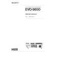
(Cassette Housing Only) 2. REMOVAL OF DECK PARTS 2-1: LINK GEAR (R) / CLUTCH GEAR (Refer to Fig. 2-1) 1. Unlock the support (1). 2. Remove the BOT Sensor Cover and BOT Reflector. 3. Unlock the 3 supports (2). 4. Remove the Side Bracket R2 and Spring Earth. 5. Remove the Flap Lever, Link Gear (R) Cam Gear Assy and BOT Lever. NOTE When installing the Link Assy and Link Gear (R), align the timing Marks. Fig. 2-4 2-5: CASSETTE SIDE L (Refer to Fig. 2-5) 1. Unlock the 2 supports (1). 2. Remove the Cassette Side L 3. Remove the Pack Spring. 4. Remove the Locker Spring. 5. Unlock the support (2). 6. Remove the Locker L. 2-2: TOP BRACKET/TAPE PIECE GUIDE (Refer to Fig. 2-2) 1. Unlock the 4 supports (1). 2. Remove the Top Bracket. 3. Remove the Side Bracket Ri and Side Bracket L. 4. Unlock the support (2). 5. Remove the Joint Gear. 6. Remove the Bracket R Spring.
Fig. 2-3 Fig. 2-6
Electrical Adjustments
3. ADJUSTMENT PROCEDURE Read and perform these adjustments when repairing the circuits or replacing electrical parts or PCB assemblies. CAUTION When replacing Cs or transistors, use only specified silicon grease (YG6260M). (To prevent the damage to IC�s and transistors.) 3-1: PG SHIFTER Fig. 2-7 NOTE 1. Install the Tension Band Assy without twisting it. 2. Oil (kyoudo oil slaidasu #150) the area marked with A in Fig. 2-7. 2-8: REEL DISK (Refer to Fig. 2-8) 1. Remove the Reel Disk S and Reel Disk T. 2. Remove the 2 polyslider washers. CONDITIONS MODE-PLAYBACK Input Signal-Alignment Tape (JG001C) INSTRUCTIONS 1. Playback the alignment tape. (JG001C) 2. Press both Tracking AUTO key on the Fig. 3-1-A
Fig. 2-2 2-3: LINK ASS�Y (Refer to Fig. 2-3) After removing in the direction (A) of Link Assy, remove the Link Assy in the direction (B). NOTE Install the (B) first, then install the (A). 2-4: CASSETTE SIDE R (Refer to Fig. 2-4) 1. Unlock the 2 supports (1). 2. Remove the Cassette Side R. 3. Remove the Pack Spring.
Fig. 3-1-B
Fig. 2-1
Recommended Safety Parts
Item
M101 M2001 M2003 UN4001 R512 R520 R525 R537 R1087 C504 C505 C506 D504 D506 D512 D513 D514 D515 D517 IC501 IC502 IC1004 Q501 Q506 Q509 Q511 Q513 L501 7501 F501 TU6001
Part No.
1596P48001 1510398028 1589V11003 A4B411B500 R3X28A563J R3X181820J R3X181010J R635U22R2J R635812R7J P22228104K CA3PF0KL3M CA30309L3M D410S1NB60 D13T0MA020 D2BT0AK040 D13TGMA020 D28T100090 D13TGMA020 D94T01501B I0Q90431L0 I0QA97810F I05S07291S TBWT009260 TC80049080 TBWT009260 0002500450 TAWT0984K0 029X000070 0481290054 080PT1R602 0162701008
Description
MOTOR, LOADING MXN - 13FB09C CAPSTAN DD UNIT F2QTB2T MICRO MOTOR EP13CC CYLINDER UNIT ASSY A4B411B500 R, METAL OXIDE 56K OHM 2W R, METAL OXIDE 82 OHM 1W R, METAL OXIDE 1.0 OHM 1W R, FUSE 2.2 OHM 1/2W R, FUSE 2.7 OHM 1W CMP 0.1 UF 250V CC 0.0033 UF 250V CC 0.0033 UF 4KV DIODE S1NB60 DIODE, SILICON GMA-02-BT DIOOE, SCHOTTKY BARRIER AK04V0 DIODE, SILICON GMA-02-BT DIODE, RECTIFIER 210009 - TA2B1 DIODE, SILICON GMA-02-BT DIODE, ZENERUZ-15BCB-TA IC NJM431L IC NJMT810FA IC TA7291S TRANSISTOR, SILICON 2S8926(ST)-AA TRANSISTOR, SILICON 2SC4908 TRANSISTOR, SILICON 2S8926(ST)-AA PHOTO COUPLER TLP621(GR) TRANSISTOR, SILICON 2SA984K-AA COIL, LINE FILTER 5510V-03330 TRANSFORMER, SWITCHING 8129005 FUSE 21801.6 R F UNIT MRF7-UB43
Fig. 2-5 2-6: BRAKE BRACKET (Refer to Fig. 2-6) 1. Remove the Main Brake Spring, S-S Brake Spring, Joint Arm Spring and T-S Brake Spring. 2. Remove the 2 screws (1). 3. Remove the screw (2). 4. Remove the Brake Bracket. 5. Remove the Sub Brake 5, Sub Brake T, Main Brake S Assy and Main Brake T Ass�y. 6. Remove the Joint Arm. 7. Remove the Reflector LED 2. 2-7: TENSION BAND (Refer to Fig. 2-7) 1. 2. 3. 4. 5. 6. Remove the Tension Arm Spring 1. Remove the Tension Arm Spring 2. Remove the Tension Adjust. Remove the Tension Arm Ass�y. Remove the Tension Band Ass�y. Remove the Tension Lever 2 Ass�y.
Cassette Housing Exploded View
|
|
|
> |
|